Crank-connecting rod

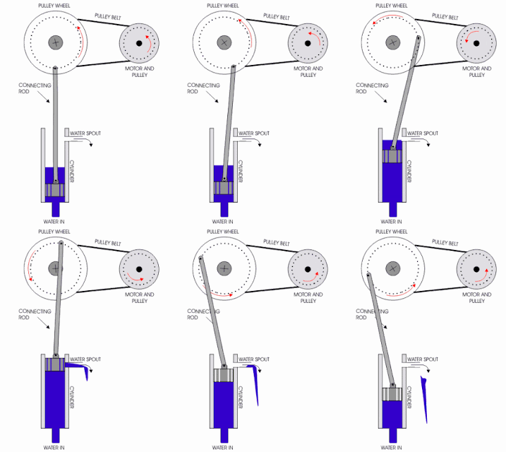
Crank-connecting-rod is a Mechanism for transformation of rectilineal motion into a rotatory one and vice versa


Above, the crankshaft( in red), sometimes casually abbreviated to crank, is the part of an engine which translates reciprocating linear piston motion into rotation


Rack and pinion


The rack and pinion gear system allows rotary motion of the steering wheel to be converted to linear motion.

Cam and follower system


A cam and follower system is a mechanism that uses a cam ( blue piece) and follower to create a specific motion.  The cam is in most cases merely a flat piece of metal that has a specific shape

Gears (Wheel and Axle)


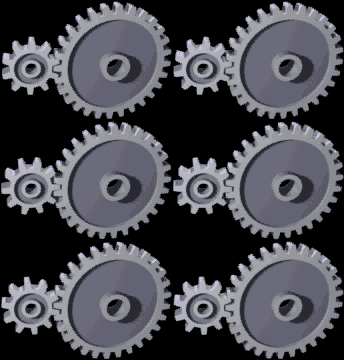
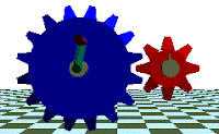
A gear is a wheel with teeth along the outer edge that rotates on an axle. By itself a gear can’t do much. But in combination with other gears, gear pairs can change the direction, speed, and torque (rotational force) of rotation.


One gear will turn in one direction and the other gear in the opposite direction.


The large gear on the left will turn more slowly than the smaller gear on the right. The large gear also can handle more torque (rotational force) than the small gear does.

PULLEY

A pulley is a grooved wheel that turns on an axle. The groove in  he wheel causes the rope or cable to ride on the wheel without slipping off.


The pulley is generally used to assist lifting heavy weights.


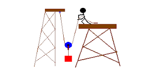
1. The pulley can change the direction of a pull. In this case, pulling down on the rope will lift the weight up. With just one pulley as shown below there is no saving of effort, but it provides a way to maneuver the weight more conveniently.


2. With the pulley arrangement shown below, less effort is required. Half the weight is supported by the overhead beam, and half is supported by the person holding the other end of the rope. The weight is shared so the human effort is less. However, now the rope will have to be pulled twice the distance. You would have to use half as much force to lift the weight, but you would have to pull the rope twice as far, as compared to the first example shown above.


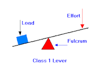
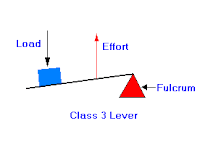
Classes of Levers

First-class levers have the fulcrum placed between the load and the effort, as in the seesaw, crowbar, and balance scale. If the two arms of the lever are of equal length, as with the balance scale, the effort must be equal to the load. If the effort arm is longer than the load arm, as in the crowbar, the effort travels farther than the load and is less than the load.


Second-class levers have the load between the effort and the fulcrum. A wheelbarrow is a second-class lever.  The wheel’s axle is the fulcrum, the handles take the effort, and the load is placed between them.  The effort always travels a greater distance and is less than the load.


Third-class levers have the effort placed between the load and the fulcrum. The effort always travels a shorter distance and must be greater than the load. A hammer acts as a third-class lever when it is used to drive in a nail: the fulcrum is the wrist, the effort is applied through the hand, and the load is the resistance of the wood. Another example of a third-class lever is the human forearm: the fulcrum is the elbow, the effort is applied by the biceps muscle, and the load is in the hand.

LEVERS

A lever is a simple machine that makes work easier; it involves moving a load around a pivot using a force. In a lever there is a load, a pivot and an Effort (force). Levers are amongst the oldest forms of mechanical system.


The input of this system is called the effort and the output is called the load. In the image, we have the input as F1 and the output as F2. The bar  pivots on a fixed point (fulcrum).